Action Types
Every step in a scenario can have a Step Definition that describes what the test automation should do when the step runs. XPressRT provides a visual configuration panel — the Step Definition Modal — with nine built-in action types covering the most common hardware test operations.
Opening the Step Definition Modal
- Open a scenario in the Test-Editor.
- Switch to Edit Mode.
- In the Steps table, click the View Step Definition button (👁) on any step row.
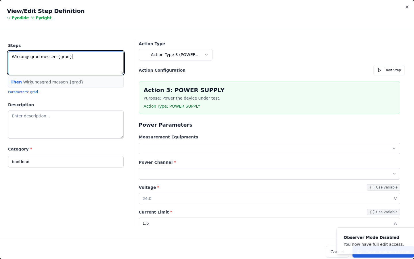
The modal has two panels:
| Panel | Description |
|---|---|
| Left — Step | The step text, a free-text description, and a category label |
| Right — Action Type | A dropdown to select the action type, followed by the action-specific configuration form |
Selecting an Action Type
Use the Action Type dropdown on the right panel to choose from the nine available types. The configuration form updates immediately. When done, click Save Implementation to write the step definition to disk.
Info
Each step definition also has a built-in Test Step button that executes only that single step in isolation — useful for verifying a configuration without running the full scenario.
Action Type Reference
1. Source Code (Manual Implementation)
Select Source Code to write or view the raw Python implementation of the step directly in the Monaco code editor. Use this for any logic that is not covered by the structured action types below.
2. Measure
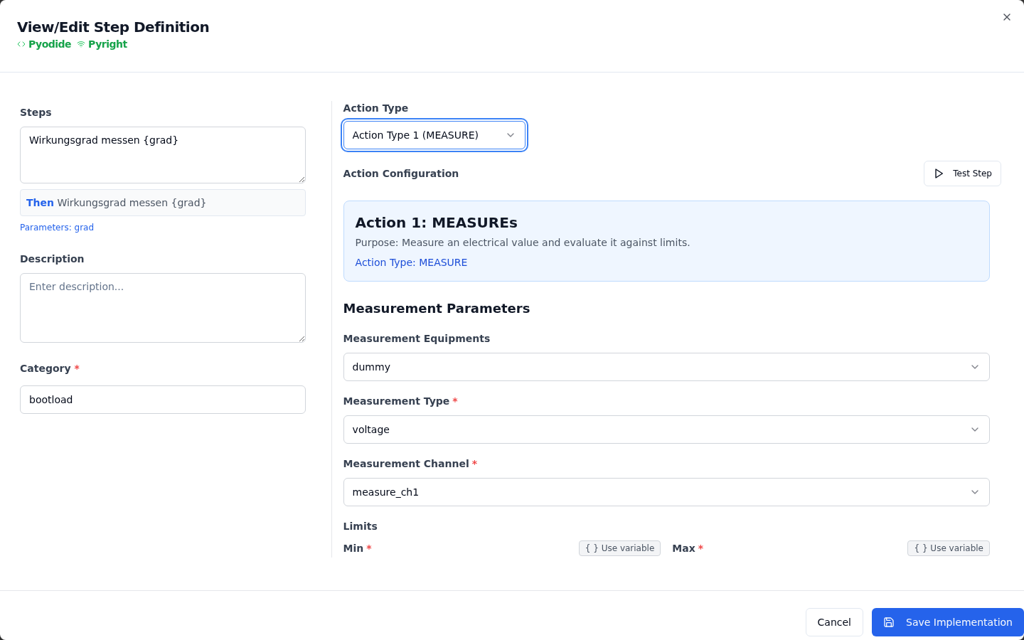
Configures the step to take a measurement from a piece of test equipment and validate it against limits.
| Field | Description |
|---|---|
| Measurement Equipment | Select the instrument from the dropdown (populated from the connected test rig) |
| Measurement Type | voltage, current, or temperature |
| Measurement Channel | The specific channel or terminal on the selected instrument |
| Limit Min | Lower bound of the acceptable range |
| Limit Max | Upper bound of the acceptable range |
| Measurement Time | How long to sample before reading (milliseconds) |
| Averaging | Number of samples to average |
| Tags | Optional flags: DC Voltage, DC Current, Resistance — used for result categorisation |
| On Fail | abort — stop the scenario immediately, or continue — log the failure and proceed |
| Error Code / Message | Values reported in the test report when this step fails |
3. Switch Matrix / Relay
Controls a relay or switch matrix to route signals on the test bench.
| Field | Description |
|---|---|
| Measurement Equipment | The instrument controlling the matrix |
| Matrix | The matrix or module identifier |
| Channel | The relay channel to control |
| State | on — close the relay, off — open the relay |
| Switch Delay | Time to wait after switching before continuing (milliseconds) |
| On Fail | abort or continue |
| Error Code / Message | Reported on failure |
4. Power Supply
Controls a benchtop power supply — voltage, current limit, and output state.
| Field | Description |
|---|---|
| Measurement Equipment | The power supply instrument |
| Power Channel | The output channel (e.g. power_supply1) |
| Voltage | Target voltage in volts (e.g. 12.0) |
| Current Limit | Maximum current in amps |
| State | on — enable the output, off — disable it |
| On Fail | abort or continue |
| Error Code / Message | Reported on failure |
5. Wait / Delay
Introduces a timed pause in the test execution — useful between operations that require settling time.
| Field | Description |
|---|---|
| Measurement Equipment | Optional — some delay implementations are equipment-specific |
| Delay Time | Duration to wait in milliseconds |
| On Fail | abort or continue |
| Error Code / Message | Reported on failure |
6. Communicate
Sends messages over a communication bus (e.g. CAN, LIN, Ethernet) and waits for expected reactions.
| Field | Description |
|---|---|
| Measurement Equipment | The communication interface |
| Send Messages | List of messages to transmit. Each entry has: ID, delay before sending, and message name |
| Expected Reactions | List of responses the test expects to receive. Each entry has: ID, delay tolerance, and message name |
| On Fail | abort or continue |
| Error Code / Message | Reported on failure |
7. User Input
Pauses test execution and displays a prompt to the operator. Use this for manual inspection steps or decisions that cannot be automated.
| Field | Description |
|---|---|
| Message | The text shown to the operator in the prompt dialog |
| Severity | info (blue), warning (yellow), or error (red) — controls the visual style of the dialog |
| Interaction Mode | confirm-only — operator clicks OK to continue, yes-no — operator selects Yes or No |
| Picture | Optional image file path shown alongside the message (e.g. a wiring diagram) |
| On Fail | abort or continue (applies when operator selects "No") |
| Error Code / Message | Reported when operator responds negatively |
8. Serial Number
Captures or validates the serial number of the device under test.
| Field | Description |
|---|---|
| Scope | global — one serial number per test run, per-scenario — each scenario records its own |
| Show Input Prompt | When enabled, a dialog is shown to let the operator enter the serial number manually |
| On Fail | abort or continue |
| Error Code / Message | Reported on failure |
9. RPC (Remote Procedure Call)
Invokes a method on a registered remote device (e.g. a microcontroller running the XPress Remote library) and optionally reads its return value.
| Field | Description |
|---|---|
| Measurement Equipment | The remote device identifier |
| RPC Method | Select from the available methods registered by that device |
| Dynamic Config | Key–value fields specific to the selected method (populated automatically) |
| On Fail | abort or continue |
| Error Code / Message | Reported on failure |
10. Programming
Flashes firmware or a configuration to the device under test.
| Field | Description |
|---|---|
| Programming Equipment | The programmer / flasher instrument |
| Firmware Path | File path to the binary or hex file to flash |
| On Fail | abort or continue |
| Error Code / Message | Reported on failure |
On-Fail Behaviour
Every action type exposes two failure handling options:
| Option | Behaviour |
|---|---|
abort |
The scenario stops immediately at this step. All subsequent steps are marked as Skipped. |
continue |
The failure is recorded in the report but execution continues with the next step. |
Use abort when a failure at that step makes further steps meaningless or unsafe (e.g. the device is not powered). Use continue when you want to collect as much diagnostic data as possible in a single run.